Cycflix: Exercise Powered Entertainment

Cheesy title, I know but it got you to click. Basically this project uses an Arduino Nano connected to a stationary exercise bike to control the streaming of Netflix on a PC, I tried to get it to work with just a Raspberry Pi but I ran into problems with finding a browser which could stream Netflix on the Pi and controlling said browser with selenium. On Firefox, you need the Widevine extension which isn’t supported on the Pi so it couldn’t stream Netflix, I found a Chromium browser someone made especially for streaming Netflix on the Pi but Google stopped supporting the Chromedriver on the Pi so I couldn’t control it. I did find an old chromedriver but I couldn’t get it to work.

Here’s is the link  to the Instructables post detailing how I made it

Measuring Temperature From PT100 Using Arduino

I posted another Instructable, this time about reading the temperature from PT100 using an instrumentation and differential amplifier. There’s abundance of LM35 temperature measurement on the site so decided to post about the PT100, might come in handy for the students doing Instrumentation in my college in the future. Also gave Autodesk’s new Circuits.io a try, to see what its like. It lets you build circuits on a breadboard and simulate them, it can also simulate Arduino code but slowed the simulation down. It doesn’t let you add components to the circuit diagram, only the breadboard mode and because you can only move things in the circuit diagram it didn’t look as nice or as clear as what I built on LTspice. But the breadboard does look nice and is good for showing the circuit layout to beginners that can’t read circuit diagrams. My circuit  can be found here. It also lets you embed the simulation onto your Instructables post but it wouldn’t embed here.
full-arduino

Simple Heart Rate Monitor Using Reflective Sensor

So I’m sure all of you have seen one of theses at least once, most likely on a visit to a hospital, this device is called a pulse oximeter.20101916190410 This device measures your heart rate and oxygen levels in your blood. The way it works is but having two leds on one side of the finger, usually red and infra-red, and on the other side a phototransistor or light dependant resistor(LDR). When blood passes through your finger, a different amount of light reaches the light sensor and the output spikes because of this.

3494761408471723727You could use either the red or IR led for this but if you want to calculate the blood oxygen levels you’d need both. Oxygenated blood lets more red light through and deoxygenated blood lets more IR light through and by alternating the leds and comparing the outputs, you can calculate oxygen levels but in this project I’m just going to be measuring the heart rate.

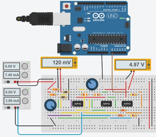
I wanted to make a simple heart rate monitor so I used cheap components that I had lying around so it definitely isn’t the best heart rate monitor around but it works. From a bit of googling I found a few other people with the same idea, one being Scott Harden which built this device a few years ago that could also be used to record an ECG, his post about building it can be found here, he also has lots of other great projects give it a visit. I used his circuit as reference from mine, I didn’t have the exact same values for each component but choose ones that were close. My circuit can be shown below:


Continue reading

Measuring Displacements Using Accelerometers: Part 3- Testing And Video

EDITED 20/05/2017

In the last post I showed the results from a test of a few millimeters but that was one of the last tests I conducted, first I tested the output of the gyroscope compared to the angle moved which I talked about before, then tested measuring a linear movement, then a movement made up of both linear and angular movements and then finally I tested the device for its initial purpose. As I already discussed testing the output of the gyroscope, I’m going to talk about the linear movement tests. I tested the device ability to measure a linear movement by mounting the sensor on a rack of a rack and pinion controlled by a servo and by controlling the angle of the servo I could repeatedly move the sensor a known distance. I don’t have a picture of the actual setup but for a visual of it, I created it on CAD.

linear_test1.JPG

So the sensor in black was laid flat on the rack and moved varying distance and the output of the accelerometer was compared to the calculated movement. The movement was calculated by using the equation for the length of an arc that the gear moved, this would be translated to linear movement to the rack.
L(\Theta)=2*\pi*r (\frac{\Theta }{360})

Continue reading

Measuring Displacements Using Accelerometers: Part 2- Comparing Methods and Integration

In the last post I discussed the methods I looked into for cancelling the gravity vectors measured by the ACC, if you haven’t seen that I would recommend reading that first. The way I compared the two methods was by seeing how well they follow the raw acceleration signal from an angular movement, this was done by mounting the sensor on the side of a servo motor and moving between different angles with varying starting positions(in reference to gravity) and magnitudes of angle change. Below is the graph from a 5-degree movement.


The blue graph is the raw acceleration signal on the Z axis,red is the cos method and the yellow is the tan method, looking at the full graph(left picture) they seem to be overlapped and looks like they both follow the raw signal fairly well but in the zoomed in picture(right), both are slightly off the middle of the raw acceleration so neither seems better than the other, the Y axis showed the same result that neither stood out. I did another test where the angle change was 35 degrees and the result of the of the two axes is below:

Continue reading

Measuring Displacement Using Accelerometers: Part 1-Calculating Gravity Vectors

So for my final year project I had to convert the signals from an accelerometer to displacements for a movement of a few millimetres and I decided to write about my experiences(mainly problems) doing this. I can’t say exactly what the device was as it was built for a research group but I’m going to go through the theory involved with getting displacements from an accelerometer. I’ll be making a few posts to cover the different topics. If You came here from the YouTube video and want to see the code you can jump to the third post. The movement I was measuring involved the sensor moving forward/backwards and upward/downward as well as the sensor tilting forward and backwards. The sensor used was an MPU-9150 which has 9 degrees of freedom(DOF), only the accelerometer and gyroscope were used in this application(3DOF each), a diagram of the axes can be seen below.mpu axes So because accelerometers measure acceleration due to gravity this would have to be canceled to isolate the acceleration caused by the movement, this wouldn’t be too difficult if all 3 axes from the accelerometer and gyro were being recorded, using some 3d vector and trig calculations this could be done easily enough but a problem I faced was having a fixed sample rate and other sensors which had to be recorded alongside the ACC and gyro, this meant that only the necessary axes from these two could be recorded. Continue reading

Automatic Webcam Tracking

For my mini project I wanted to make something that would move a around webcam to keep an object in the center of the screen. To do this I used two servos to change the x and y axis orientation of the webcam but before I got to attaching the webcam I needed to learn how to find objects and isolate them from a webcam, to do I used OpenCV and Python. The first program I made was to read in the feed from a webcam and display the normal feed, the hue, saturation and value(hsv) for the feed isolating the colour was looking for and Continue reading

Stepper Motor Control

The next motor I worked on was the stepper motor which works by turning on multiple coils in a sequence to turn the motor. The code I started with used bit banging to rotate the stepper in one direction at one speed. This code can be found here. First thing I did with this code was to have it react to a sensor, in this case a light dependent resistor(LDR), the LDR used was the NORP12 RS. Using two LDRs and the analog digital converter(ADC) to have the stepper to point in the direction of a light source, the LDRs would be mounted on the stepper so if one LDR was reading more light the stepper would move in that direction until the two LDRs were were reading the same amount of light. The code is shown below:

Continue reading

DC Motor Control

This week I worked on controlling a DC motor using the pulse width modulation (PWM) in the dsPIC30F4011 to adjust the speed of the motor. The code I started with would drive the motor at 75% duty cycle for two seconds then 25% for two seconds and repeat, this code can be found here. The DC motor pulls a lot more current than the PIC can supply so I needed to use a driver chip (SN754410NE), This chip would amplify the current enough to drive the motor. On this chip we can apply the PWM to the enable pin on either side giving us the ability to switch the chip on and off very quickly and this turns on and off the motors, this switching will then change the speed. If the enable pins were left alone the motor would just run at full speed. Continue reading